Chip Thickness Ratio- Shear Angle, Rack Angle, Derivation of formulas.
Chip Thickness ratio is defined as the ratio of the thickness of the chip before cutting to the thickness of the chip after cutting.
During cutting, the cutting edge of the tool is positioned at a certain distance below the original. This corresponds to the thickness of the chip prior to chip formation, t1, and as the chip is formed along the shear plane, its thickness increases to t2 ( after cut chip thickness).
The thickness of the chip increases after cutting primarily due to Plastic deformation. Plastic deformation is the process by which a metal permanently changes its shape or size when subjected to sufficient stress, beyond its elastic limit.

Image Source : https://www.mecholic.com/2017/02/chip-thickness-ratio-cutting-ratio-equation.html
We know that,
t1= chip thickness before cutting
t2= chip thickness after cutting
and let r be the Chip thickness ratio
Then, Chip thickness ratio

Whenever there is a high cutting ratio, it means the cutting action is good.
Now let
l1 = length before cutting
l2= length of chip after cutting
b1= width of chip before cutting
b2= width of chip after cutting
α = rake angle of tool
ϕ = shear angle
Since the volume before cutting is equal to volume after cutting. In other words, the volume of metal cut off from the workpiece is equal to the volume of the chip.
l1 b1 t1 = l2 b2 t2
Generally b1=b2
Therefore, t1 l1 = t1 l2
or, t1 / t2 =l2 / l1
Then the chip thickness ratio
r = t1 /t2 = l2 / l1
Image Source: https://www.mecholic.com/2017/02/chip-thickness-ratio-cutting-ratio-equation.html
Shear Angle: –
As the tool is forced into the material, the chip is formed by shear deformation along a plane called the shear plane, which is oriented at an angle with the surface of the workpiece known as Shear Angle. It is denoted by ϕ.
Rack Angle:-
Rack Angle is the angle between the rack face and the normal to the machine direction.
It is denoted by α.
Relation Between Chip Thickness Ratio, Shear Angle and Rack Angle:-
Diagram of angles of chip Thickness ratio separated from the above diagram:-

Where,
ϕ= Shear Angle
α = Rack Angle
t1 = uncut chip Thickness
t2 = cut chip thickness
From the angle diagram we have,
In the triangle ABC, we have
Now in triangle ABD, we have
x + 90° + (90°- ϕ) + α= 180°
x = 180° – 90° – ( 90°- ϕ) – α
x = ϕ- α
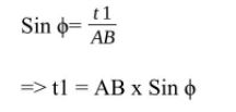
Now,
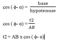
So as we know that,

Where,
E = chip reduction ratio or coefficient
So, as we know, the chip thickness ratio,
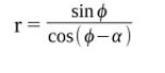
r x cos ( ϕ- α) = sin ϕ
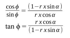
r x (cos ϕ x cos α+ sin ϕ x sin α) = sin ϕ
r x cos ϕx cos α= ( 1 – r x sin α) x sin ϕ
Factors on which chip thickness ratio depends:-
1) Type of material.
2) Type of cutting fluid.
3) Geometry of cutting tool.
4) Cutting variables such as feed rate, speed, and depth.
Coefficient of chip contraction or Chip reduction Coefficient
Coefficient of chip contraction, or Chip reduction Coefficient is the inverse of Chip Thickness ratio. It is a quantitative measurement of plastic deformation occurred during the cutting process.
Chip reduction ratio ( k ) = t2/t1 = l1/l2 =1/r
The chip reduction ratio increases when:-
* the cutting angle increases or the positive rake angle decreases.
* The nose radius increases.